Intro
Most online VHDL descriptions of JK flip-flops (FF) are based on “processes” or circuit functionality (behavioral). Is it possible to simulate them only by constructing the circuit structure of the JK flip-flop?
JK FF Review
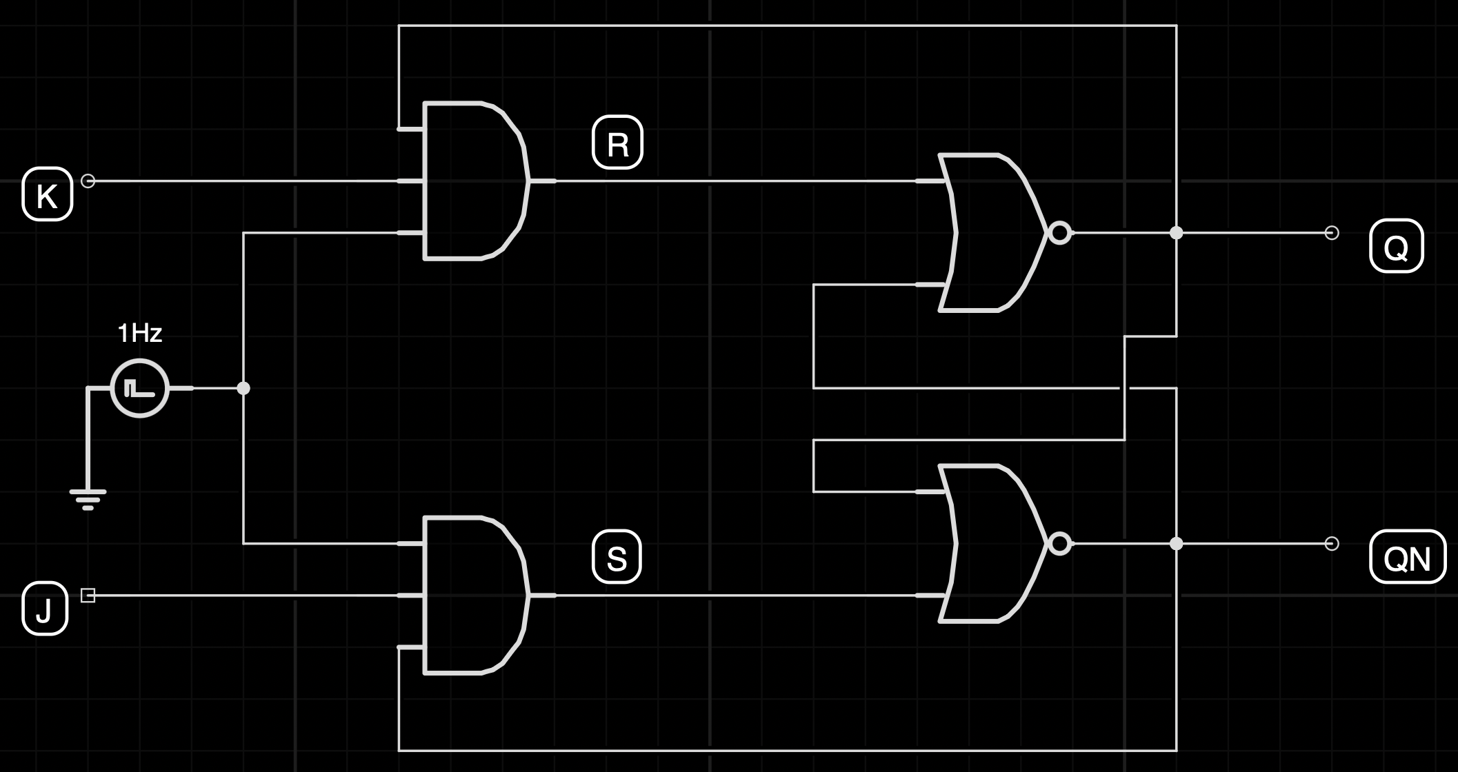
The circuit structure is JK FF is very familiar to everybody, which is:

The corresponding truth table is shown below:
| C | J | K | Q | Q̅ |
|---|---|---|---|---|
| ↑ | 0 | 0 | latch | latch |
| ↑ | 0 | 1 | 0 | 1 |
| ↑ | 1 | 0 | 1 | 0 |
| ↑ | 1 | 1 | toggle | toggle |
| x | 0 | 0 | latch | latch |
| x | 0 | 1 | latch | latch |
| x | 1 | 0 | latch | latch |
| x | 1 | 1 | latch | latch |
where “latch” represent the Q output remembers whatever the last stored value was. “Toggle” means to flip Q, i.e. 0 -> 1, 1 -> 0. “↑” means the clock signal in a leading edge.
Problem
First try
Write the following content in JKFF.vhdl:
|
|
Then write a testbench file to test the behavior of this circuit, you will find it will not work well.
Reason
The reason (probably, only personal view) is that JK FF have two layers of feedback (instead of SR FF, which just have one), since we loop our output Q not only to the NOR gates, but also AND to our initial inputs J and K. This confuse the compiler because the resultant signal changes so fast and maybe not have a stable consequence, so the compiler do not know how to respond to this kind of feedback.
So we introduce some delay in the gates to simulate the reality closer.
Solution
Adding delay in the gates
We write the following content in another file JKFF.vhdl:
|
|
And run the following JKFF_tb.vhdl:
|
|
Results
We will get the following waveform:

There are several strange things happen here:
What happen before around 30 ns?
The Q and QN oscillates at the same pace. Why? It’s because both J and K are zero. For a JK FF, this means to remember the last value. But the last value of Q and QN are both zero (we initialize them in the JKFF.vhdl file):
|
|
This is invalid and unstable! So they oscillates with a period of 0.2 ns, which is exactly the delay time of the NOR gates.

OK, if instead we initialize the Q and QN a valid value, say Q_int=0 and QN_int=1 like this (in JKFF.vhdl file):
|
|
Since they are valid, hence stable, Q and QN will not oscillates as expected:

Why not toggle successfully?
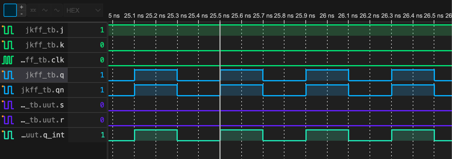
At around $t = 70$ ns, both J and K are 1. This means at the leading edge of the clock signal clk, Q and QN should both flipped! But according to the waveform, they tried but failed, with a tiny pulse around that time.
I tried several clk pulse width and analysed the JK circuit in “slow-motion” carefully (Try this! Very surprising!). Finally I figured it out:
It’s because JK FF don’t want the clk signal be high for too long. This is because if the clk line hold high for a sufficient long period, the signal at Q and QN will “backpropagate” (Haha just borrow the term) to the inputs, continue to control whether or not the J and K signal should come in. If we increase the so-called “duty-ratio” of the clk signal, we will see these:


Some value of duty ratio (e.g. 0.65) happen to toggle the Q successfully, while others do not.
You can think of what value could the duty ratio be? (Given the clock cycle and the propagation delay of all gates) This is a very intereting yet tedious problem to consider. But as long as you understand why Q oscillates, you understand this.
Therefore people say that there are no “JK latches”.
Conclusion
The VHDL realization of a JK FF can be achieved by introducing propagation delay to the gates.
